This tutorial will walk users through an example DegenGeom file, illustrating the various representations and relevant metadata for each level of degeneracy. For example, the thick surface representation includes each surface node along with surface normal directions for each panel. The panel representation will include the location of each thin-surface patch along with the local centroid, local camber, etc. The stick representation will include outlines of the primary feature lines of components (such as wing leading and trailing edges), local moments of inertia, thickness to chord ratios, etc. Points will contain information such as component mass, moments of inertia, wetted areas and volumes, and much more.
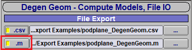
Along with OpenVSP, a series of MATLAB functions are provided to visualize different levels of model degeneracy. These functions are located in the “matlab” folder and are listed below. To use these functions, the *.m DegenGeom option flag must be selected when running the export. The MATLAB scripts will only accept this DegenGeom format.
An OpenVSP model may be subsequently reduced into geometrically simpler representations from thick surfaces to plates to sticks, and finally, to points all while maintaining metadata about the model. This process is called DegenGeom. Different model representations may be used for different purposes. For example, the plate representation is used to supply the VLM surfaces in VSPAERO, a stick representation may be used for a structural analysis, and the points representation may supply mass and inertia to a dynamics simulation. OpenVSP’s DegenGeom tool produces a file with each level of degeneracy and all relevant metadata for the model.
OpenVSP will export the airfoil distribution along a Wing component in either a DAT or BZ (Bezier) format. The number of airfoils written will correspond to the total spanwise Num U of your wing. When exporting airfoils, the window will ask to save an Airfoil Metadata file rather than the DAT or BZ. This metadata file provides the context and location of each airfoil file that is also written out in the process.
The untrimmed CAD export types (STEP/IGES) produce a standardized CAD file built from the native OpenVSP Bezier surfaces in the model. The surface resolution displayed in the workspace defined by Num U, Num W, clustering, etc. has no effect on the resulting CAD files. Once you have chosen a set of components and a format type, the Untrimmed STEP/IGES Options menu will appear. In this window, the desired length units must be defined along with a tolerance (accuracy) for the export. Multiple other options are available enabling users to tailor the export format toward their CAD program of choice. For example, some programs will import the model with gaps or breaks in wing trailing edges or fail to accept non-split surfaces. In these cases, options are provided to address these issues.
Unfortunately, the rules defining the STEP/IGES format are relatively loose and were defined by committee. This means that writing a STEP or IGES file is much easier than reading one. If your CAD program has issues reading an OpenVSP CAD export, try different options to see if you have some success. It may also help to write a STEP/IGES from the CAD program and compare or to research what specific style of STEP/IGES that CAD program expects.
An OpenVSP model may be exported as a triangulated mesh such as an STL, TRI, OBJ, etc. For each of these formats, the resolution of the exported mesh will directly reflect the resolution of the OpenVSP tessellation shown in the workspace (Num U, Num W, clustering, etc.). Triangulated mesh formats will typically export as a single mesh or multi-solid mesh as appropriate for each type without providing the user an option. However, STL exports may be set up to write either a single mesh or a tagged multi-solid file. STL formats also have the option of exporting Prop components at the origin rather than in their set location in the model. This is useful when you wish to export a mesh of an isolated rotor at the origin without having to move it in the model.