The ability to control most cross-section sizes by area and height-to-width ratio were added in OpenVSP version 3.26 to the existing width and height controls. Two of the available options are selected and fixed while the others are deactivated and solved to fit the constraints. This feature is particularly useful when designing flow-through components where deliberate, simple parametric variation of sectional area is desired. Many cross-section types take advantage of these new constraints including those more advanced or complex. For example, the radii of a rounded rectangle are taken into account when computing the area of such a section. In fact, because the cross-section curves are all integrable functions, the area may be computed for any arbitrary closed curve or iteratively solved to satisfy the constraints. This applies to Edit Curves as well.
The Wedge airfoil enables users to set sharp, wedged leading and trailing edges based on a maximum thickness to chord ratio and the chord location of this maximum thickness. Users may also choose to set a section along the chord of constant thickness with the Flat Up parameter which results in a six-sided section rather than a traditional wedge. The U-location of feature points on this cross-section may also be modified to attach to associated points on neighboring cross-sections.
The root and tip cap types may be altered under the More tab in the propeller component window. With these settings, you can alter the shape of the cap between flat, rounded, or sharp and also adjust the tessellation or number of interpolated lines on the cap. Similar to other caps, if you find that the root or tip cap is too sharply turning at the leading or trailing edges you can activate the Sweep Stretch button which will loft those caps a bit more and smooth the transition.
The overall tessellation of your propeller is set using the Num U and Num W parameters under the Gen tab where a larger number of points in the radial or chordwise directions will generally decrease any faceting of the blade surface. The clustering or grouping of these lines may be adjusted under the More tab where the leading edge, trailing edge, root, and tip clustering are located. Values less than 1.0 group the lines closer together in the region and values greater than 1.0 space them further apart. A value of 1.0 implies uniform or unit strength at that location. For uniform distribution, set both ends of the blade (either LE/TE or root/tip) to 1.0.
The propeller folding axis orientation is defined by two parameters, Azimuth and Elevation. In this tutorial, we demonstrate how the azimuth and elevation change the direction of the folding axis and provide useful views for observing the axis rotations. Refer to the sections below for additional details.
Azimuth and Elevation
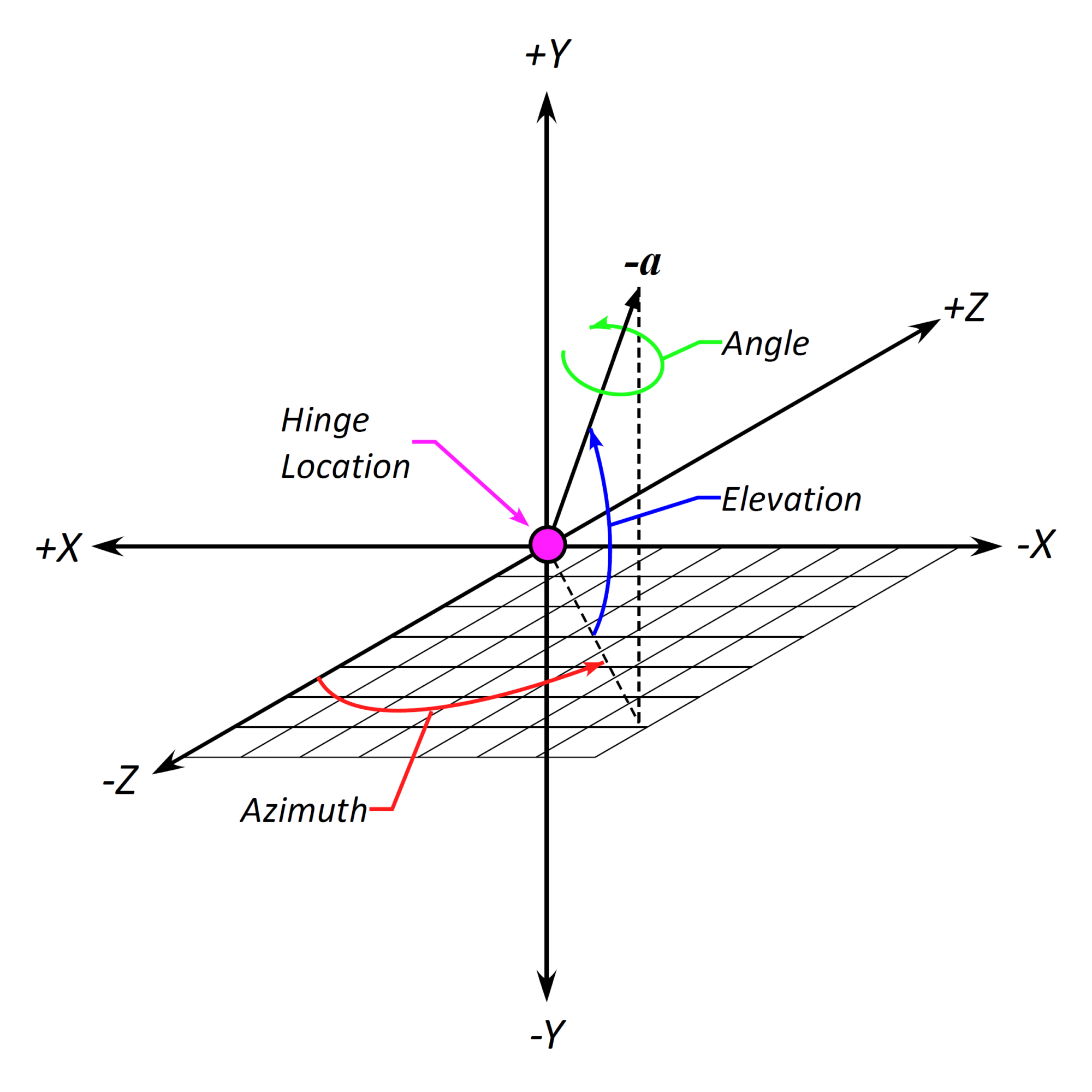
The Azimuth and Elevation are defined according to the convention shown here in which the azimuthal plane of rotation is the XZ plane or, more specifically, the rotation is about the blade feather axis (+Y in this case) and the elevation is a direct, angular ascension from the azimuth. The propeller hinge rotation axis is the vector -a in this example.
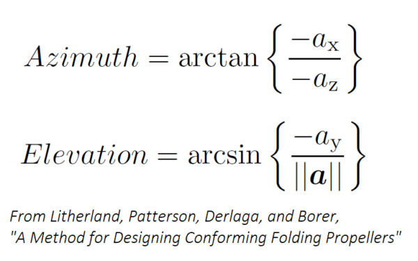
The Azimuth and Elevation may be calculated from known directional components of the rotation vector a.
The placement of a propeller folding hinge is defined by the Radial/R, Axial/R, and Offset/R parameters which adjust the location along the blade feather axis, in and out normal to the propeller disk, and “up” or “down” within the propeller disk or normal to the feather axis and thrust directions, respectively. Each of these distances are normalized by the propeller radius so that they remain independent of alterations to the propeller size. The Angle parameter sets the angular rotation about the propeller hinge axis.