Components may each be grouped into collections known as Sets in OpenVSP by choosing the individual components relevant to an analysis, assembly, configuration, or for export. Sets are intended to make it quick and easy to switch between pre-selected groups rather than individually showing or hiding components in the model tree under the geometry browser window. The Set Editor enables users to quickly add or remove components from a set, copy and paste components from one set to another, and rename sets. Individual components may also be added or removed from sets under the Set Export/Analysis box in the component window.
The root and tip cap types may be altered under the More tab in the propeller component window. With these settings, you can alter the shape of the cap between flat, rounded, or sharp and also adjust the tessellation or number of interpolated lines on the cap. Similar to other caps, if you find that the root or tip cap is too sharply turning at the leading or trailing edges you can activate the Sweep Stretch button which will loft those caps a bit more and smooth the transition.
The overall tessellation of your propeller is set using the Num U and Num W parameters under the Gen tab where a larger number of points in the radial or chordwise directions will generally decrease any faceting of the blade surface. The clustering or grouping of these lines may be adjusted under the More tab where the leading edge, trailing edge, root, and tip clustering are located. Values less than 1.0 group the lines closer together in the region and values greater than 1.0 space them further apart. A value of 1.0 implies uniform or unit strength at that location. For uniform distribution, set both ends of the blade (either LE/TE or root/tip) to 1.0.
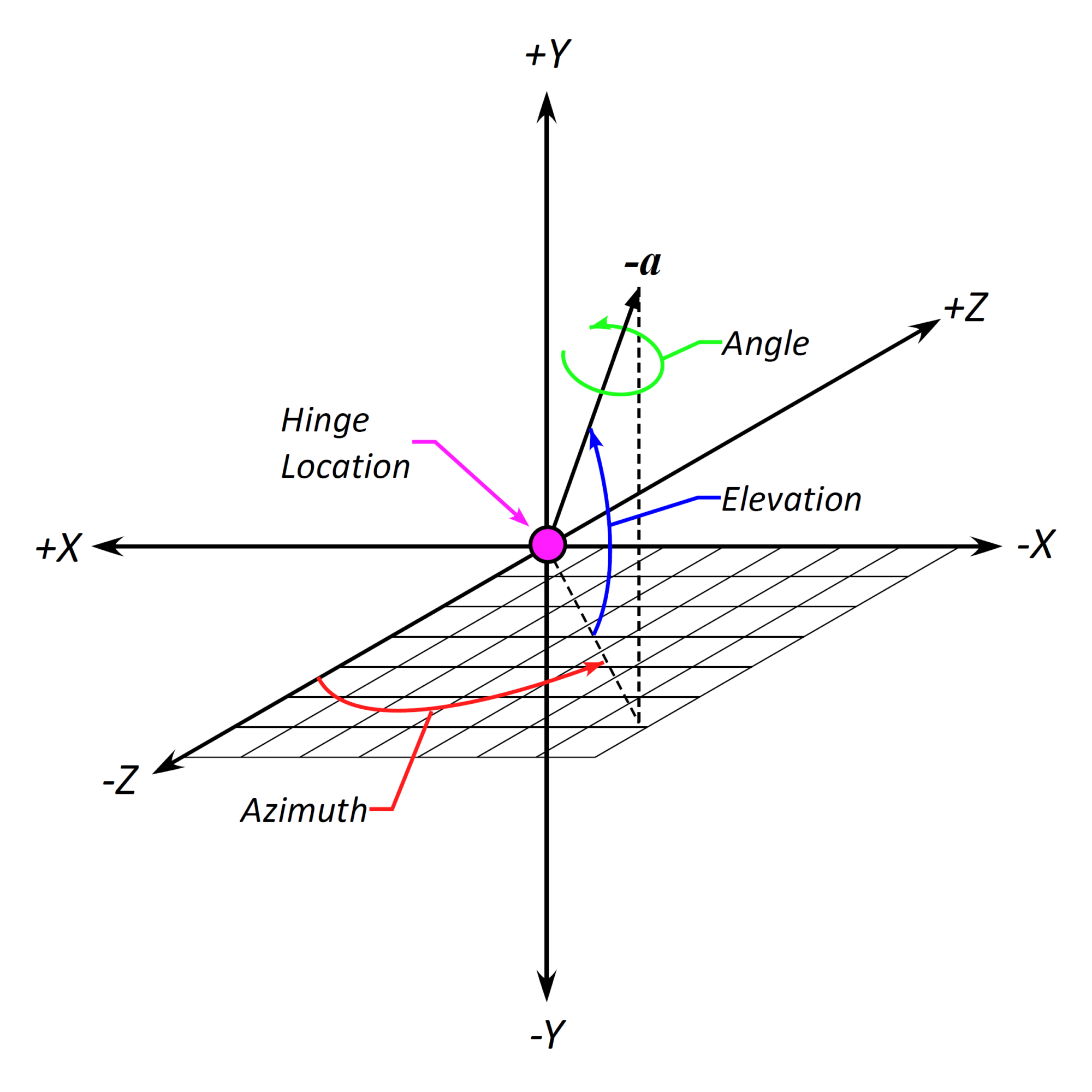
The propeller folding axis orientation is defined by two parameters, Azimuth and Elevation. In this tutorial, we demonstrate how the azimuth and elevation change the direction of the folding axis and provide useful views for observing the axis rotations. Refer to the sections below for additional details.
Azimuth and Elevation
The Azimuth and Elevation are defined according to the convention shown here in which the azimuthal plane of rotation is the XZ plane or, more specifically, the rotation is about the blade feather axis (+Y in this case) and the elevation is a direct, angular ascension from the azimuth. The propeller hinge rotation axis is the vector -a in this example.
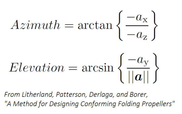
The Azimuth and Elevation may be calculated from known directional components of the rotation vector a.
The placement of a propeller folding hinge is defined by the Radial/R, Axial/R, and Offset/R parameters which adjust the location along the blade feather axis, in and out normal to the propeller disk, and “up” or “down” within the propeller disk or normal to the feather axis and thrust directions, respectively. Each of these distances are normalized by the propeller radius so that they remain independent of alterations to the propeller size. The Angle parameter sets the angular rotation about the propeller hinge axis.
As covered in minor detail in the Symmetry with Propellers tutorial, there are multiple ways that you can modify propeller symmetry. These applications are not limited to only traditional propellers but for any geometric shape that you wish to have both axial and planar symmetry about different points. In this example, we show how to create a reflected, counter-rotating propeller across the XZ plane and also how symmetry can be ineffective at producing left/right same-direction propellers. To accomplish such a feature, a copy of the primary propeller should be made and placed on the opposite side manually. For the purposes of actuator disk modeling, this left/right anti-symmetry isn’t an issue and the direction of propeller rotation may be simply altered with the RPM setting.